DVT IDE for VS Code SystemVerilog User Guide
Rev. 24.1.7, 9 April 2024
- Installation
- User Interface
- Predefined Projects
- Build Configurations
- Project Natures
- Non-top files
- default.build
- Auto-config
- Simulator Log-config
- Emulating compiler invocations
- Multiple .build Files
- Compatibility Modes
- Paths
- Strings
- Comments
- Environment Variables
- Including Other Argument Files
- Build Persistence
- All Build Directives
- SystemVerilog OVM or UVM Library Compilation
- Xilinx Libraries Compilation
- Intel(Altera) Quartus Libraries Compilation
- Questa Libraries Compilation
- Use of External Programs
- Compile Checks
- Quick Fix Proposals
- Content Assist (Autocomplete)
- Hyperlinks
- Show Usages
- Show Readers or Writers
- Show Call Hierarchy
- Show Type Hierarchy
- Show Constraints
- Show Instances
- Peek Exploration
- Refactoring
- Override Functions
- Generate Setters and Getters
- Code Factory
- Code Formatting
- Breadcrumb Navigation Bar
- > Diagrams
- Syntax Coloring
- Tooltips
- Workspace Symbols
- Views
- Quick Search in Views
- Content Filters
- Macros Support
- Inactive Generates Code Highlight
- Database Out of Sync Notification
- External Tools Integration
- UVM Support
- Scripts
- Custom Scripts
- SCM Checkout Hook
- Memory Monitor
- Application Notes
- Handy VS Code Documentation Pointers
- What is New?
- How to Report an Issue?
- Legal Notices
- Third Party Licenses
- Q & A
Table of Contents
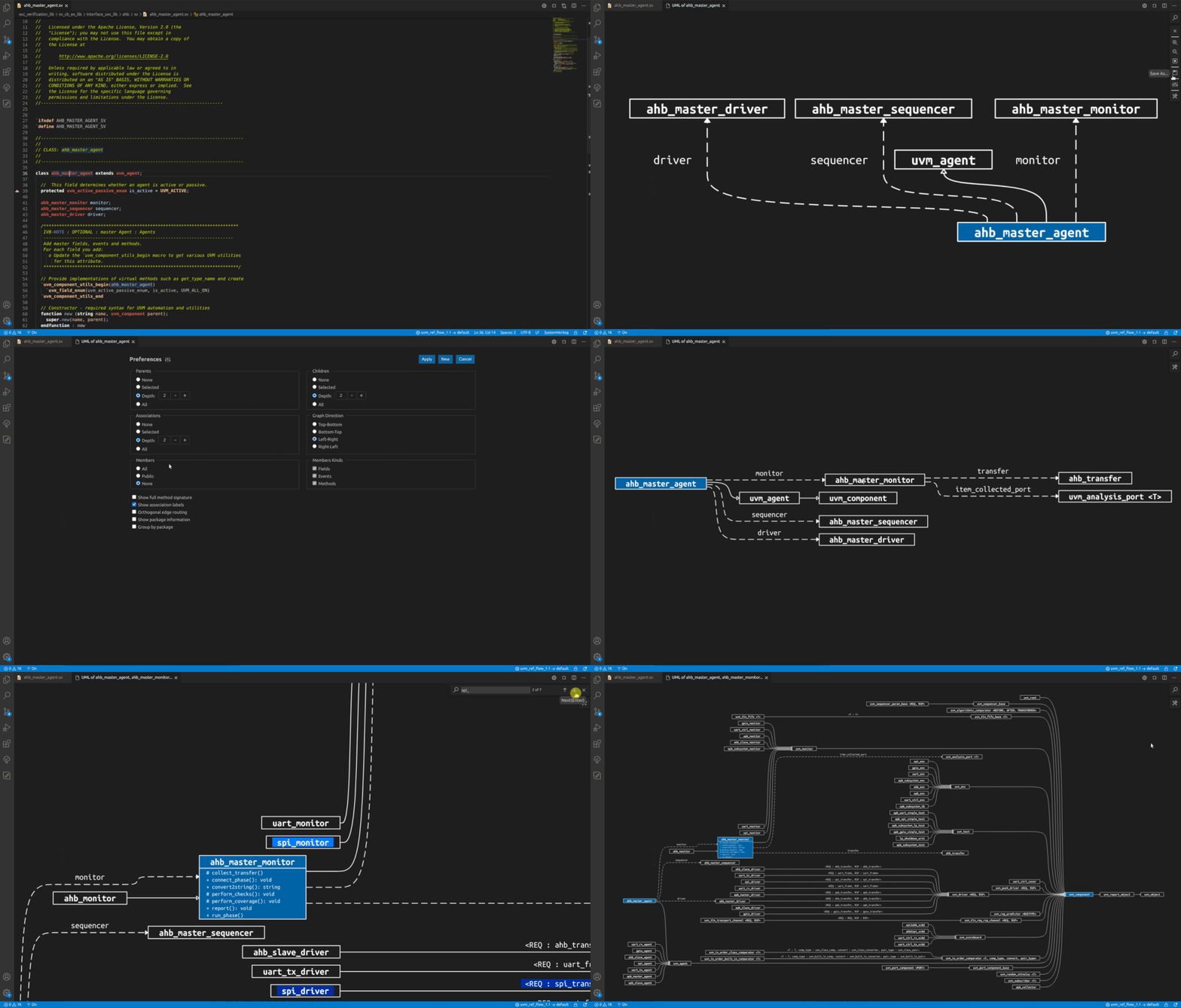
To create UML diagrams, place the cursor on the name of a class, then use the "DVT: Show Diagram" command and select "UML Diagram".
A diagram is created around a set of relevant classes you specify. For example, when you decide to show parents, children, or associations by using the available preferences, it applies only to selected classes.
The selected classes are colored with yellow fill. To add or remove an element to or from the current selection, use the "Select/Deselect Type" context menu actions.
